
Design guide / Wide-voltage input
9–36 V DC Input in Vehicles and Plant Cabinets
Six GEOLiNK models accept 9–36 V DC. This guide draws that window against the common 12–19 V band.
Surge, reverse polarity and brown-out levels are not on the cards. Confirm them before design-in.
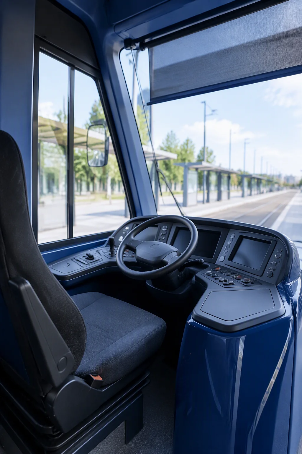
01 / The two windows
Two input windows on one scale.
A 12–19 V board covers a nominal 12 V rail. The 9–36 V window covers 12 V and 24 V vehicle rails and a 24 V plant supply.
A load dump is not a steady 24 V rail, and a 36 V ceiling is not a surge rating. Below 9 V the board is outside its window.
02 / Beyond the range
The input range is the first question, not the last.
The card states a window. Four other checks decide whether the board survives.
-
Surge immunity
A 9–36 V rating covers steady input. Load dump and inductive switching sit outside it; no surge level is stated.
-
Reverse polarity
No reverse-polarity rating is stated. If the input can be miswired, add a diode or ideal-diode circuit and check the loss.
-
Brown-out
Below 9 V the board is outside its window. Decide whether the system rides through, resets, or needs a hold-up capacitor.
-
Grounding
Use one return at the DC input, a short chassis bond and a separated analog return.
03 / Model values
Six models accept 9–36 V DC.
Values are from the current cards, not a measured input draw.
| Model | Form factor | Input | Power rating | COM | LAN | Operating |
|---|---|---|---|---|---|---|
| AD600Z3AW | 155 × 117 mm | 9–36 V DC | Not stated | 6 | 2 | −20 to +60 °C |
| MSK-TL5003AW | 146 × 102 mm | 9–36 V DC | 90 W | 5 | 2 | −20 to +60 °C |
| PNM-5210 | 120 × 120 mm | 9–36 V DC | Not stated | 5 | 4 | −20 to +60 °C |
| RP7003AW | 146 × 102 mm | 9–36 V DC | 120 W | 6 | 2 | −20 to +60 °C |
| TL500Z3AW | 155 × 117 mm | 9–36 V DC | 90 W | 6 | 2 | −20 to +60 °C |
| UT1003AW | 146 × 102 mm | 9–36 V DC | Not stated | 6 | 2 | −20 to +60 °C |
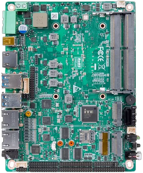
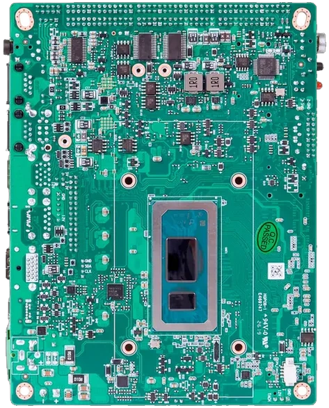
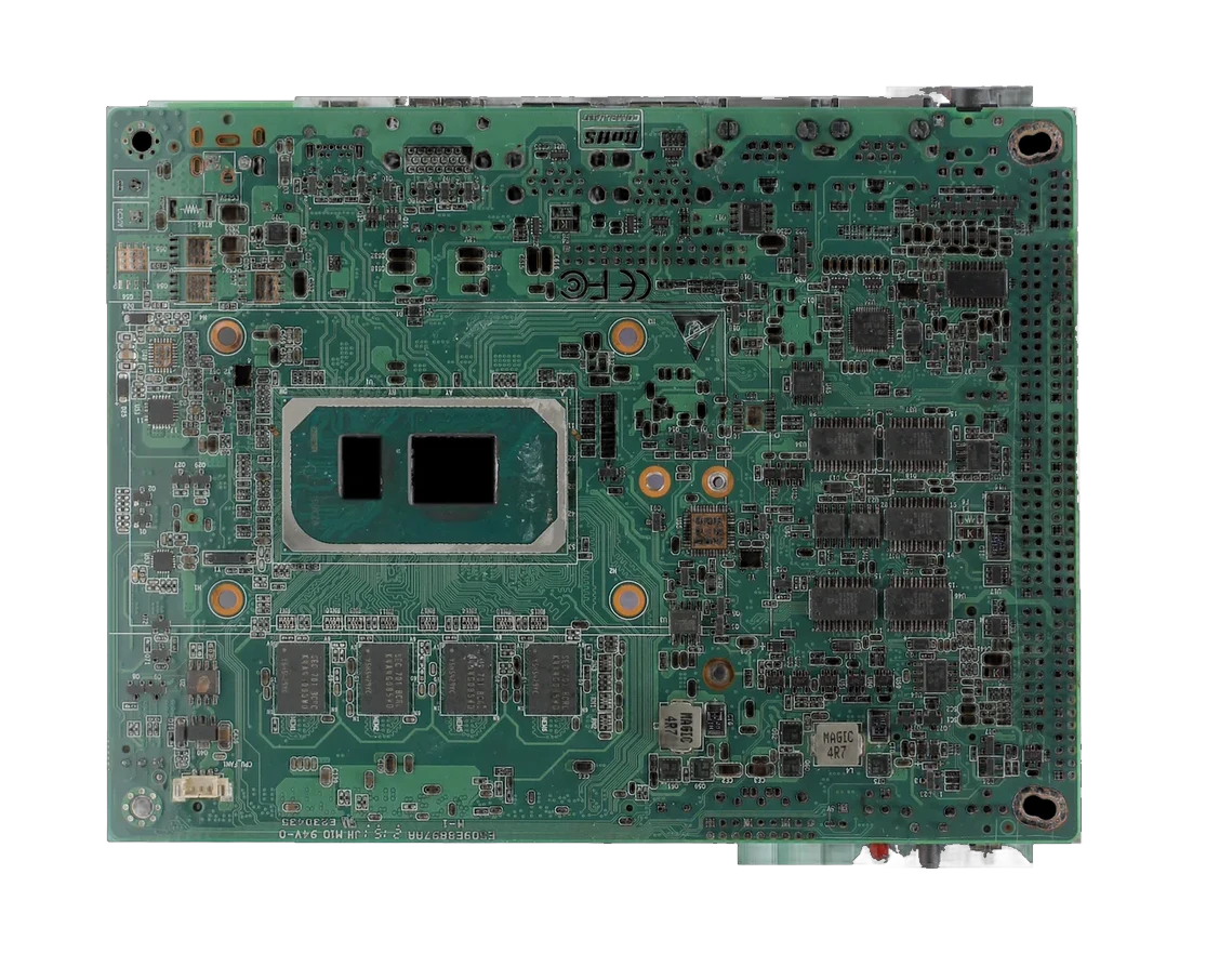
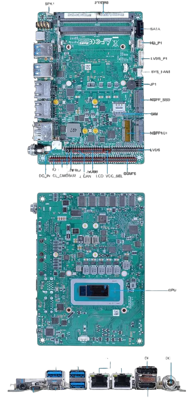
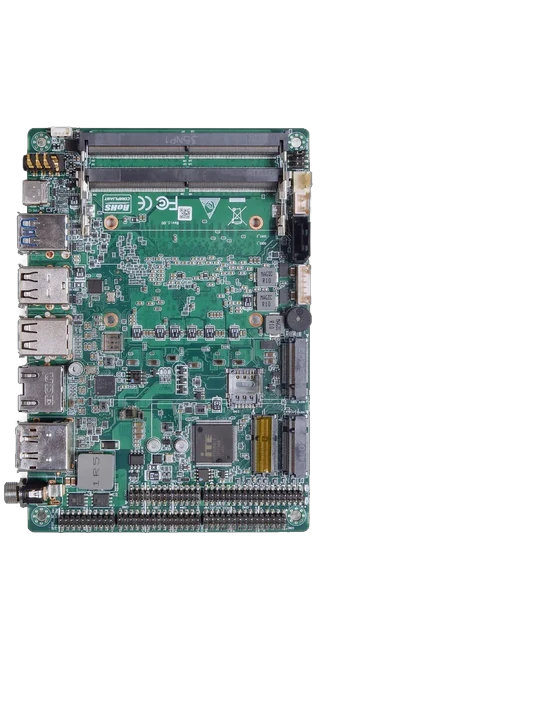
AD600Z3AW 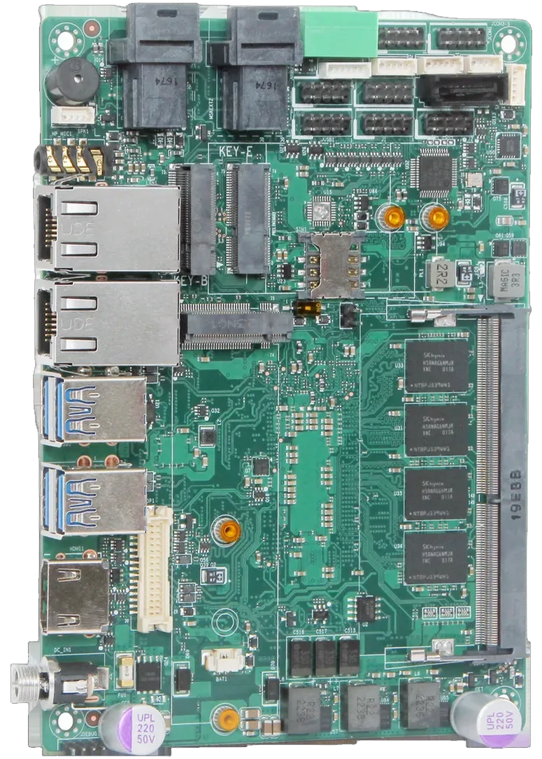
MSK-TL5003AW 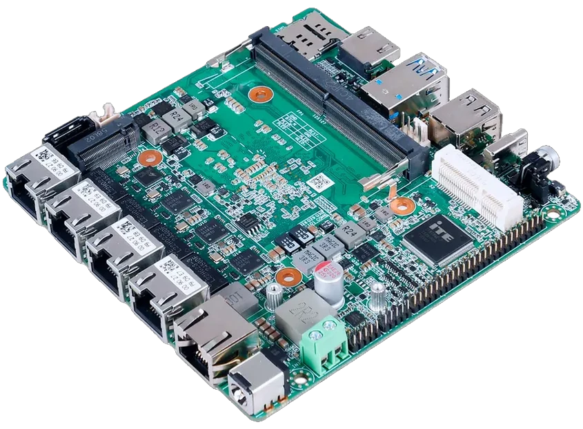
PNM-5210 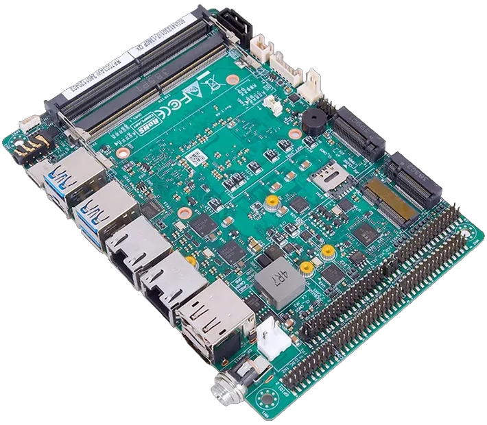
RP7003AW 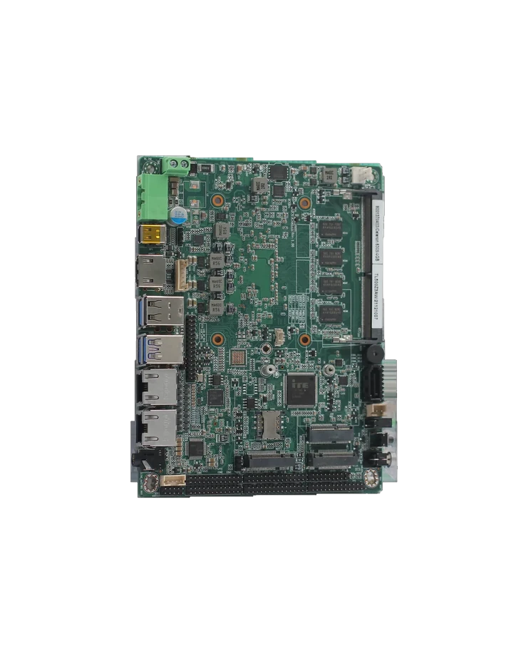
TL500Z3AW 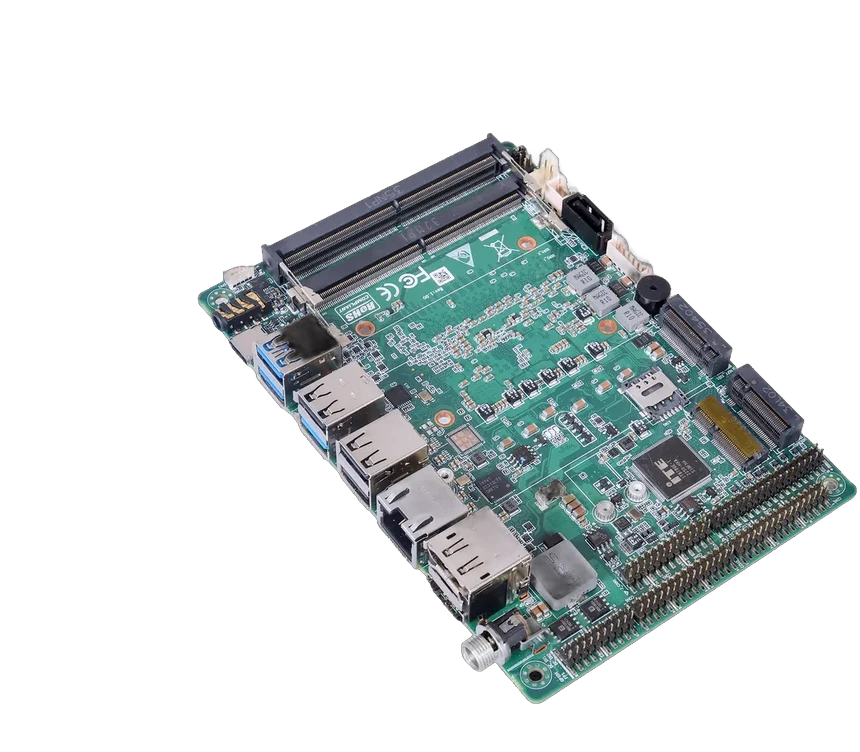
UT1003AW
04 / Protection checks
Five checks, in this order.
Each check closes a gap the input range leaves open.
Input range
Measure the supply under load. A 24 V DIN-rail supply can sit at 26–28 V unloaded.
Surge and transient
Ask for the test level and waveform. If none is documented, add an external TVS at the connector.
Reverse polarity
Decide whether the input can be miswired in service. Add protection or key the connector.
Brown-out
Set the reset threshold and test a cold crank or relay drop. Log the restart.
Grounding
Check the return path, chassis bond and cable shield. Test emissions in the finished enclosure.
05 / Open items
Three questions this guide cannot settle.
Does this guide apply to my model?
Only for the six models in the table. Other cards list a different input range or do not state 9–36 V.
Is the protection level documented?
Not on the cards. Surge, reverse polarity and brown-out are not stated as test levels.
What must I validate in my enclosure?
Input voltage under load, transient response, reset behaviour at the low end, and the ground return.
06 / Shortlist
Turn the voltage question into a model shortlist.
Send the supply range, load and I/O count. We reply with the closest model within 24–48 h.